面内振动和面外振动 In- & Out-of-plane
4D data are mandatory for accurate in- and out-of-plane measurements
Many MEMS have, by design or unintentionally, both in-and out-of-plane displacements components. The accurate decomposition of their displacement into these two is essential for analyzing and optimizing the dynamical and frequency response of MEMS.
With a single instrument, DHMs measures topography as a function of time, i.e. 4D data (3D + time). It contains, for any sample geometry and motion, all the information needed to determine quantitatively both in- and out-of-plane components.
Alternative systems for MEMS analysis combine measurements acquired with several independent sensors, which in many cases makes impossible correct measurements.
The need for 4D data to accurately measure in-plane and out-of-plane vibration components is illustrated by the applications presented in the tabs on this webpage.
- In-plane larger than feature sizes
- Non planar structures
- Other examples of complex motion

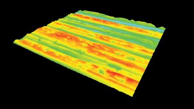
Large in-plane displacements
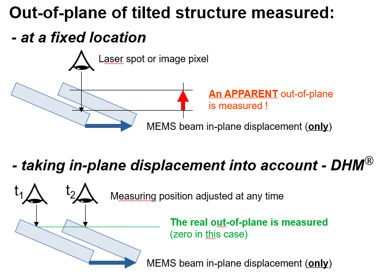
In-plane displacements are critical for out-of-plane measurements when their range is large relative to the moving parts features size. This is the case when :
- thin arms move over distances larger than their width,
- surfaces perforated with sacrificial holes move over distances larger than the interstices between holes, or
- patterned surfaces move over distances larger than the pattern sizes.
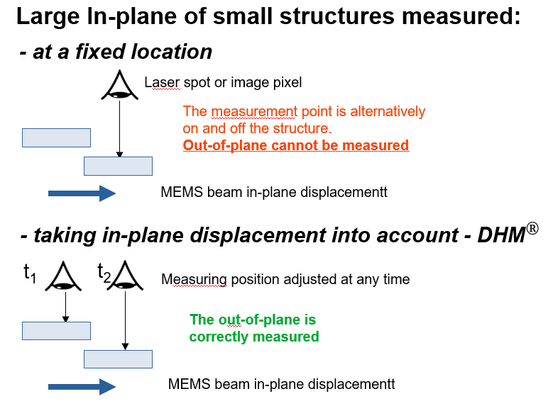
Such large in-plane movements can lead to erroneous out-of-plane characterization when measurements are taken at a fixed spot, as illustrated in the figure on the right.
The DHM 4D dataset provides reliable measurements for any cases, enabling:
- to track in-plane over large fields of view, with sub-pixel resolution,
- to measure the out-of-plane continuously on the same point of the moving surface, following the in-plane motion, and
- to measure out-of-plane over spots as small as one pixel, a size generally smaller than MEMS feature size.
An out-of-plane measurement spot must necessarily follow the in-plane movement.
[:de]
Application to a micromotor
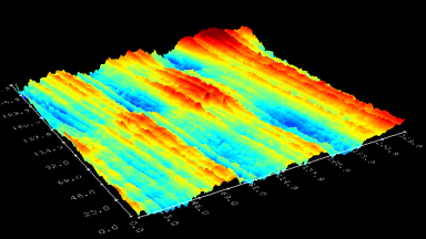
This microsystem has thin beams that move in-plane over large distances compared to their width. The decoupling of in-plane and out-of-plane displacements of one of its parts is explained below and illustrated in the figure on the left.
Our MEMS Analysis Tool software allows to track the in-plane displacements of any feature or moving element. It uses this in-plane displacement information to define an out-of-plane measurement spot fixed in the referential of the moving part. This procedure can be used for characterizing both rigid and deformable structures.
In this micromotor case, the in-plane motion is measured by tracking the upper-left corner of the moving structure. The first graph below the 4D map shows the X displacement versus time. The same is done for its Y position (not shown here).
This XY (in-plane) information is used to maintain the out-of-plane measurement spot at the same point on the sample surface over time. Here, the measurement spot has been assigned right beside the structure corner (square labeled “1”). The second graph below the 4D map shows the Z displacement versus time.
This method enables perfect decoupling of in- and the out-of-plane (XYZ) components.
Sample by courtesy of TU Chemnitz, Germany.
In-plane displacements of a non planar surface
Often, MEMS structures that translate, rotate or deform in-plane are:
- not perfectly flat
- not parallel to the in-plane motion
- not perfectly smooth, or
- not rigid
These deformations can lead to erroneous measurements of out-of-plane displacements, apparent but not real, when taken at a fixed point that does not follow the movements of the structure, as illustrated in the figure on the right.
The DHM 4D data set provides reliable measurement in any cases, as it enables:
- to determine in-plane translation and rotation parameters by shape registration,
- to compensate for any in-plane motions. By using the registration parameters, the moving part is positioned in a coordinate frame in which it is static as a function of time.
- to calculate the actual out-of-plane displacement of any point of moving part surface. Real out-of-plane vibration maps are generated.
An out-of-plane measurement spot must necessarily follow the in-plane movement.
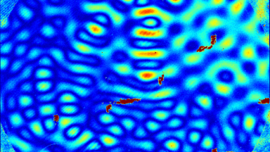
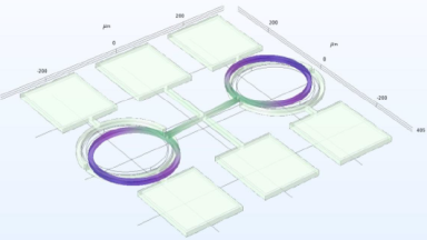
Application to a tunable ring resonator
A tunable resonator consists of a spectacle-shaped structure attached to flexible arms that rotate in-plane around a vertical axis center. This structure is not flat, as shown on the left figure.
The figure below compares the out-of-plane amplitudes maps of the left circle of the spectacle obtained, compensating or not for in-plane movement, measured for frequencies between 48 and 54 kHz. The maximum out-of-plane value measured at resonance (52 kHz) is:
- Non compensated: 18 nm (apparent, non real out-of-plane)
- Compensated: 4 nm (true out-of-plane)
Sample by courtesy of ENS Montréal, Canada. More on this application.

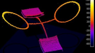
Wattwins 2DOF time-base oscillator
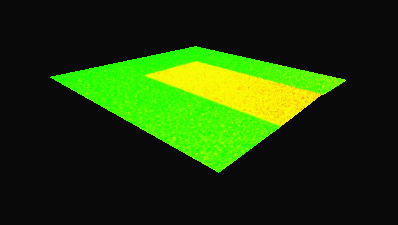
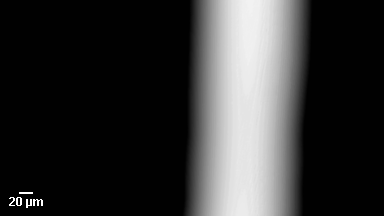
The Instant-Lab at the Swiss Institute of Technoloy of Lausanne (EPFL) is developing a Wattwins 2DOF time-base oscillator for mechanical wristwatches without escapement (IsoSpring concept), machined in silicon by DRIE.
Measuring both in- and out-of-plane displacements of the part transmitting the movement to the watch mechanism is especially of first importance for minimizing losses and optimizing the efficiency of the mechanisms.
The 4D data set is shown on the upper image on the right. The in-plane motion is measured on the intensity images and removed on the 4D data to retrieve pure out-of-plane measurements shown on the bottom image.
Sample by courtesy of The Instant-Lab at the Swiss Institute of Technoloy of Lausanne (EPFL)
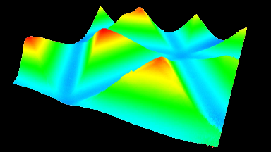
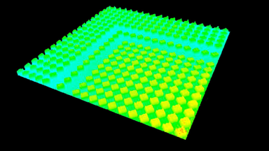
Deformation of watch oscillator along its period cycle
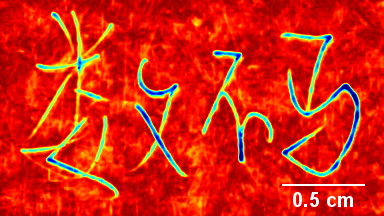
The out-of-plane deformation of a silicon based watch oscillator is a parasitic movement that induces a loss of energy for the watch, reducing its autonomy.
The figure on the left shows how DHM® measures the out-of-plane deformation of an oscillator along its periodic cycles.
The time-sequence of 3D topographies (4D set of data) is registered to compensate for the in-plane motion (XY). It provides a data set for which the oscillator appears superimposed in time, from which the out-of-plane vibrations are easily extracted with high accuracy.
The left images show the in-plane motions and the out-of-plane vibration after compensating the in-plane motion.
Sample by courtesy of LVMH